Projection-based measurement review
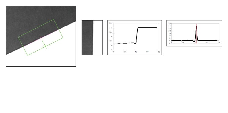
Projection-based measurement uses a straightforward algorithm that is robust to both lighting variation and irregular edges, while still being extremely fast. The basic algorithm can be described in the following steps:
Figure 1 – Steps to locate an edge using projection: (i) align the search region (left) using rotation along the horizontal axis (second from left), (ii) generate a projection of pixel intensities along the horizontal (shown) or vertical axis (second from right) and (iii) locate an edge by finding a peak in the projection’s first derivative or gradient (right).
i. Alignment of a search region along the horizontal axis by means of rotation.
ii. Projection of the pixel intensities within the aligned search region along the horizontal or vertical axis to produce an average onedimensional (1D) intensity profile.
iii. Analysis of the 1D profile to find a certain number of transitions. For example, a typical method used to locate a transition involves finding the peaks in a projection’s first derivative (i.e., the gradient peaks) whose values lie beyond a certain edge threshold.
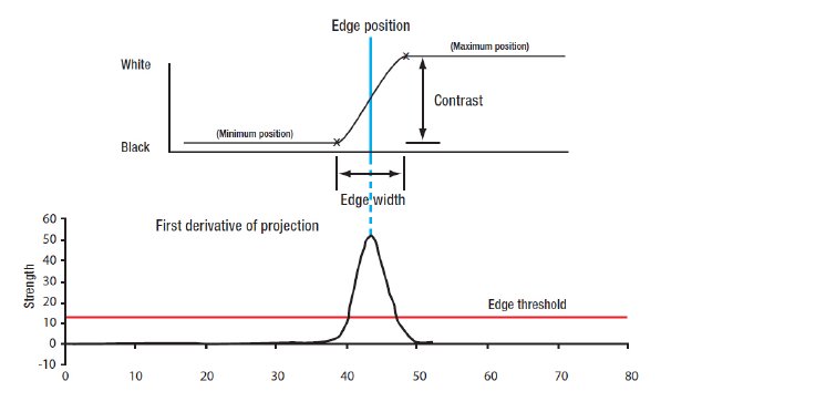
At this point, it is possible to obtain many characteristics of the resulting edge
Figure 2 – The edge characteristics position (top), strength (bottom), contrast (top), polarity (top) and width (top) explained.
The Measurement tool can calculate more than just a single edge. By pairing edges, the tool finds what is referred to as a stripe. A stripe has characteristics in addition to those of an edge; these are, namely, the stripe width and the number of individual edges inside it.
The Measurement tool can also automatically rotate the search box to determine the best edge/stripe. Additionally, the tool is able to locate multiple edges/stripes within a single search box. Multiple edges/stripes have an additional characteristic over a single edge/stripe, which is the spacing between edges/stripes.
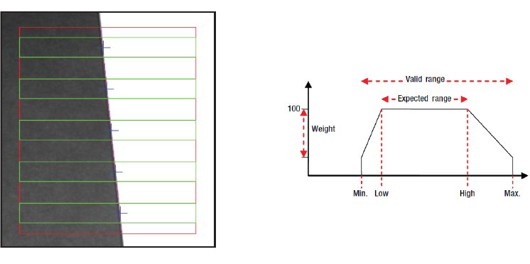
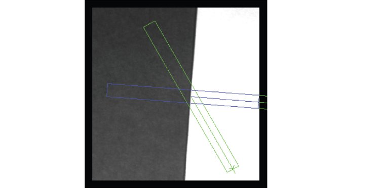
Finally, since the projection-based method only returns a single point along a 1D profile, it is not possible to determine the angle of each edge. However, the Measurement tool addresses this shortcoming by automatically employing multiple search sub-boxes within the main search box to find the exact angle of each edge.
Figure 3 (left) – Multiple search sub-boxes (in green) within the main search box (in red) are automatically employed to determine the angle of an edge.
Figure 4 (right) – The new scoring function response with its adjustable points.
Enhancements to the Measurement tool
Given its popularity among machine vision developers, Matrox Imaging recently made several enhancements to its Measurement tool. The following sections describe these key enhancements.
New scoring functions
A central change to the measurement module is the introduction of new adjustable scoring functions. These provide a method to select the desired edges based on the weighting of specific characteristics. There is a scoring function for each of the following characteristics: strength, position, contrast, spacing, number of inside edges, width, and radius (for circles discussed in the next section).
The response (i.e., shape) of the scoring function for each characteristic is determined by four parameters: (i) the minimum value accepted (i.e., Min.), (ii) the minimum value that scores 100% (i.e., Low), (iii) the maximum value that scores 100% (i.e., High) and (iv) the maximum value accepted (i.e., Max.). In addition to these basic parameters, a fifth parameter, weight, can be assigned to each characteristic to give it more or less importance in the global score. The bigger the weight, the more penalized a given characteristic will be for values lying outside the expected range but still within the valid range(s). An example of a scoring function response is shown in Figure 4.
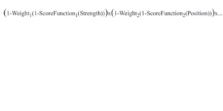
The shape of the new scoring functions is made flexible through the ability to specify these five parameters whose values can be set dynamically. These new scoring functions allow for the creation of selection thresholds per characteristic. The individual scoring functions are combined to produce the global score using a multiplication that acts as a logical AND operation (Figure 5) that merges the effects for an overall selection.
Figure 5 – Calculation of global score.
New circle marker
A key addition to the Measurement tool is the circle marker. The principle behind the circle marker is quite simple: a circle is found by fitting multiple edge positions located in a radial fashion inside an annular search region. Just like the edge and stripe markers, the user can set the polarity, defined from the inner to the outer radius, an edge threshold to filter unwanted sub-positions, and the new maximum association distance control (discussed in a following section) to select only the sub-edges closest to the circle.
Support for simplified fixturing
With the introduction of simplified fixturing, it was critical to make sure that the Measurement tool could make use of it. Through simplified fixturing, the Measurement search box can be automatically repositioned based on the positional results from another tool such as Model Finder or Pattern Matching.
World units throughout
To simplify both the setup and the usage of the results of a given marker, the support for world units was extended to the whole tool. A user can now specify the search box parameters (position, size, and angle), as well as other parameters, like spacing, in world units while being able to get the results in either world or pixel coordinates.
Maximum association distance
As mentioned earlier, the Measurement tool uses multiple search sub-boxes to calculate the exact angle of the edge. However, it can happen that these sub-boxes contain more than one possible sub-edge that could match with the edge found in the main search region. Sometimes, the correct sub-edge is not the one with the highest score. In general, false sub-edges are far from the true edge found within the whole main search box and could be eliminated based on this distance. The maximum association distance does just this by eliminating the sub-edges that are too far from the true principal edge.
Search box clipping
Since the Measurement tool is based on the projection of a search box, the search box was previously required to fit entirely in the image to find the marker. This is acceptable when the position, size, and angle of the marker is fixed but problematic when the angle search is enabled, since the search box can lie outside the image at some angles. It is even more troubling when combined with the simplified fixturing where the position and angle of the search box is unknown beforehand. To overcome this hurdle, automatic clipping has been implemented to resize the search box so that it fits entirely in the image, and thus ensures that an edge can be found.
Figure 6 – Automatic clipping of the search box.
Enhancements in action
The next section uses examples to illustrate the new features of the Measurement tool.
Finding the top and bottom edges
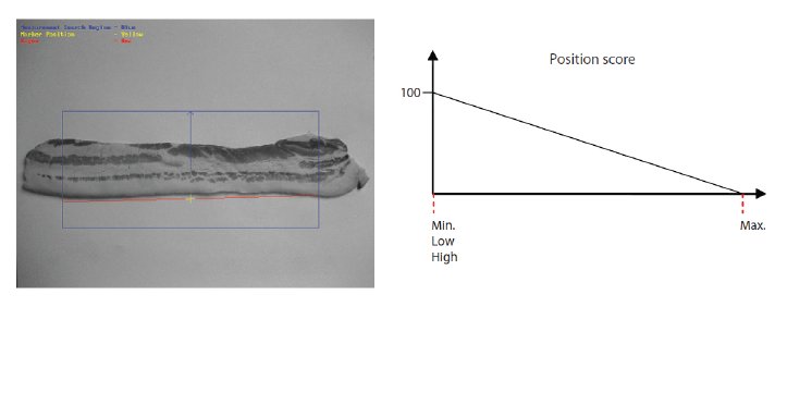
The following example shows how to find the outer edges in a complex scene with multiple edges. First, the strength scoring function, which is set by default to a ramp response, must be given a flat response. Second, the position scoring function must be set to favor either the bottom or the top edge (from the search direction), by respectively specifying a decreasing or increasing ramp response.
Figure 7 – To locate only the bottom edge (red) in search box (left), the position scoring unction is set to a downward ramp response (left). The top edge is located by setting the position scoring function to an upward ramp response (not shown).
Finding the widest stripe
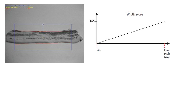
By giving the strength scoring function a flat response and by setting the width scoring function to an upward ramp response, the widest stripe in a complex scene with multiple edges can be found.
Figure 8 – The widest stripe (red) within a search region (left) is found by setting the width scoring function to an upward ramp response (right), thus favoring the widest stripe.
Finding the appropriate circle
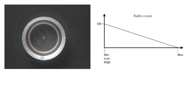
Locating and measuring a specific circle within an annular search region is a common requirement. Using the radius scoring function and the maximum association distance parameter allows the appropriate circle to be selected. In this example, the strength scoring function was given a flat response and the radius scoring function was set to a downward ramp response in order to find the smallest circle. To ensure that only the edges closest to the correct circle are contributing to the fit, a maximum association distance is specified.
Figure 9 – The appropriate circle (red) is found and fitted within an annular search region (left) by setting the radius scoring function to a downward ramp response (right), as well as specifying a maximum association distance.
Incomplete circle with noise
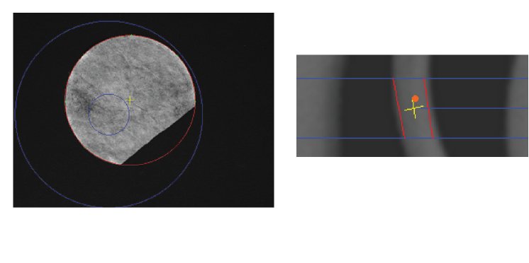
In many applications, the circle to locate and measure may be partially broken and there might be some noise in the annular search region. By increasing the edge threshold to remove unwanted sub-positions found due to noise and by using the maximum association distance so that all the edges contributing to the circle are near the circle, the correct circle can be found.
Figure 10 (left) – Adjusting the edge threshold and setting a maximum association distance allows an incomplete circle with noise to be found and fitted.
Figure 11 (right) – Only the stripes that enclose the user-defined inclusion point (orange dot) are considered (only the stripe with the highest score is returned as the result).
Inclusion point
Finally, another advanced feature called the inclusion point allows a stripe marker to be selected based on whether a user-specified point is inside or outside the stripe. All these enhancements are available as of Matrox Imaging Library (MIL) 9 Processing Pack 2 (including the integral examples featured above) and Matrox Design Assistant 2.3.
i Maximum sub-position distance in Matrox Design Assistant.
ii With the exception of the circle marker.
Direkt Link: Matrox Imaging Library:
http://www.rauscher.de/...
RAUSCHER
Johann-G.Gutenberg-Str. 20
D-82140 Olching
Telefon +49 81 42 / 4 48 41-0
Fax +49 81 42 / 4 48 41-90
E-Mail: info@rauscher.de
www.rauscher.de
